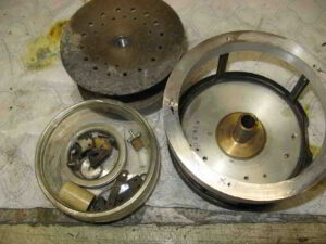
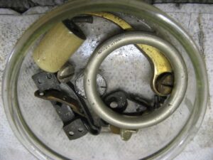
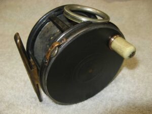
This is a picture of a completed project I undertook using a badly damaged reel. The following photos will take you through many of the processes I go through to restore a reel.
Stage 1
90% of the parts already to hand to start the rebuild. A replacement outer rim on the frame made from PA6 aluminium secured in place with 10BA lost head screws.
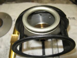
Stage 2
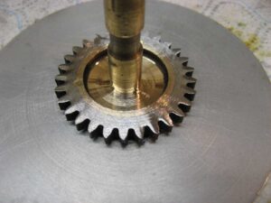
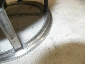
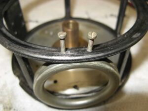
This photo shows a replacement rim secured to the centre hub of the winding plate spindle. The winding plate was machined back to a point where the original Hardy stampings were retained.
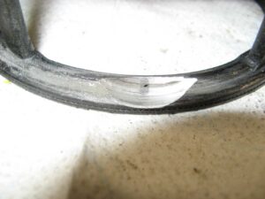
Stage 3
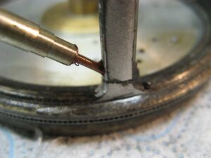
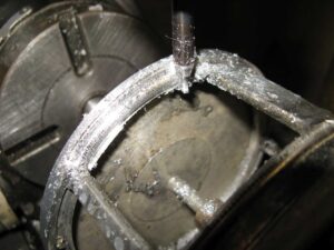
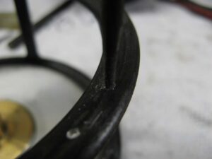
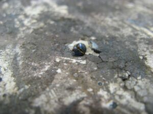
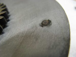
One method I use to repair a cracked frame/pillar. A compression fitted 10BA brass screw.
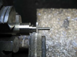
Stage 4
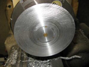
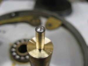
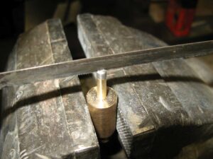
A mandrel screwed into the winding plate spindle so that I could hold it in the lathe and clean up the bearing surface.
Stage 5
The beginning of machining the replacement front rim of the frame.
Stage 6
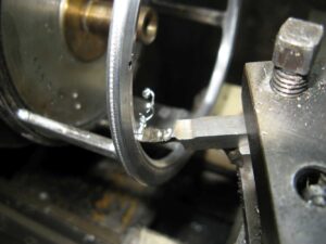
Milling the nice inner curves on the front flange.
Stage 7
Hand finishing the milling marks using 400 grit paper.
Stage 8
Machining the curvature on the front of the replacement flange and the inside diameter.
Stage 9
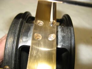
Checking the fit of the spool to the frame and note the mistake I made with my first attempt at drilling the hole positions to fit the flange to the pillars.
Stage 10
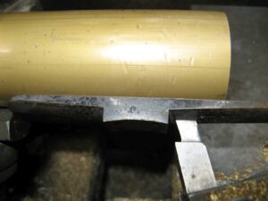
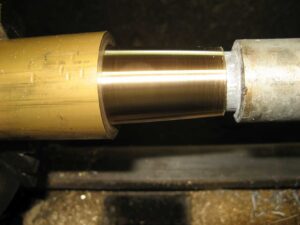
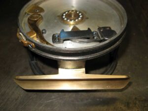
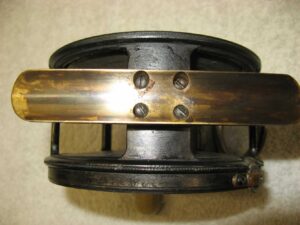
A large tube of admiralty bronze with the correct inside diameter/radii for the foot. This is set up in the lathe with an original Hardy foot I borrowed from another one of my reels pressed up against it to to give the correct tapered angle for the lathe cutting tool.
Stage 11
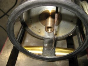
Machining the foot angle to the correct length.
Stage 12
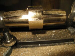
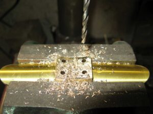
Both ends of the replacement foot cut to length and now set up in my milling machine to cut the foot to the correct width. By doing it this way I can make three separate reel feet from one piece of admiralty bronze.
Stage 13
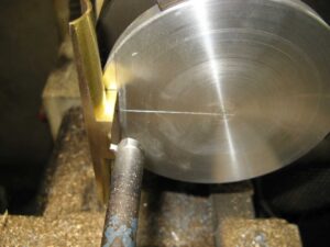
The machined foot super glued on its edge so that I could cut the inner curve of the foot to suit the diameter of the reel. This is a delicate operation and care is needed not to dislodge the foot.
Stage 14
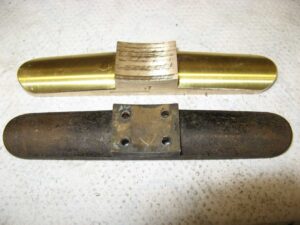
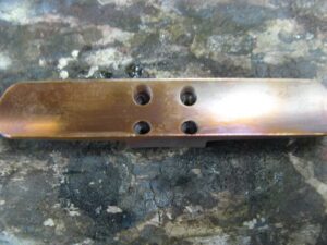
The completed foot with rounded ends filed and papered to the correct Hardy contours.
Stage 15
Time to look at the condition of these parts and to make sure they are all viable.
Stage 16
Checking the position of the rotating line guide before I hand cut the cut-out on the new front flange. Note at this stage I have finished the acid etch, black lead/bronzing and lacquering.
Stage 17
I had only one original brass foot retaining screw which I used as an example before I made four high carbon steel ones. The thread form for these screws are based on the vintage British Cycle Thread with a diameter of only 0.102 inches and I made a tap and die to produce these threaded parts.
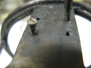
Stage 18
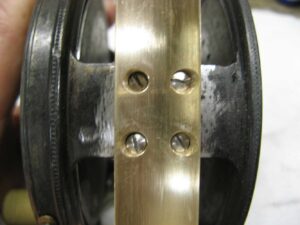
Using a Dremel I cut out the undercut for the line guide. The picture also shows an alloy epoxy I have developed to fill one of the holes I had drilled and tapped by mistake. The compound I invented is as strong as aluminium and can be black leaded.
Stage 19
Drilled and tapping the holes to hold the two pins that keep the line guide in place.
Stage 20
Testing what will be lost head threaded pins to hold the line guide. These have a sharp taper at the tip and then hacksawed off and the remaining rough end filed back to the contour of the frame.
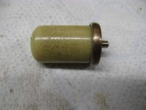
Stage 21
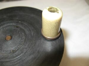
Offering up the original erinoid handle and cup to find a nice position.
Stage 22
One of two 8BA high carbon steel screws in position in a mandrel so that I could hand saw a slot into the head of the screw.
Stage 23
Heat treating the small screws.
Stage 24
Quenching the screws in water.
Stage 25
Tempering the screws to get a nice, blued finish and to soften them so that they are not too brittle.
Stage 26
Test fitting the next set of screws that will hold the spring block in place.
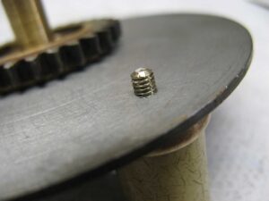
Stage 27
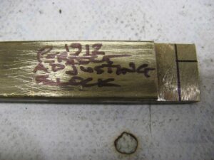
Making the stop screw for the 1912 adjusting arm.
Stage 28
The original spring was broken so a true replica had to be made using high quality spring steel hardened and tempered.
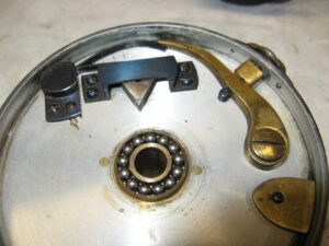
Stage 29
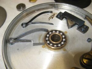
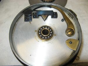
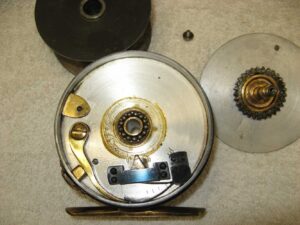
A basic dry build to make sure everything fitted and functioned as they should.
Stage 30
There was no adjusting block that came with the reel parts which were in a tatty plastic bag so a replacement needed to be made.
Stage 31
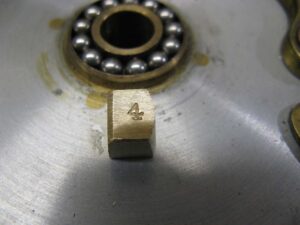
Adjusting block completed and stamped to match the reel numbering. This is not the correct font for the reel but quite close and won’t be seen when the reel is completed.
Stage 32
A nickel silver adjusting screw to go with the replacement adjusting block.
Stage 33
Block and screw testing.
Stage 34
Screw, block, stop screw and six hardened and tempered screws lightly bronzed and put in place.
Stage 35
Replacement handle wire.
Stage 36
Testing the handle on the wire and the depth of thread so that there would be the right amount of up/down clearance between the handle and cup.
Stage 37
Wire, handle, and cup tested for correct sizing.
Stage 38
Lopping off the wire.
Stage 39
Finishing off the top end of the wire.
Stage 40
The completed unit ready for fitting.
Stage 41
Loosely fitting of the handle.
Stage 42
I leave the handle wire quite long so that I can use strong pliers to lock the threads in place.
Stage 43
The end of the wire ground off using a Dremel and then carefully riveting the end flush to the winding plate. A very light touch of diluted Birchwood Casey at this point just to tone down the shiny nickel silver wire end.
Stage 44
Preparing the positioning of the foot (Reel Back) I like to use gauge blocks for this to ensure the correct positioning and to make sure it is square to the frame.
Stage 45
The Reel Back held in position with the tiniest amount of super glue so that it will be easy to remove.
Stage 46
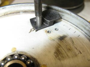
Spot drilling with an extended tapping drill I made.
Stage 47
Drilling clearance size hole through the foot.
Stage 48
60 Degree tapered countersunk holes to suit the four replacement high carbon steel screws needed to hold the foot in place.
Stage 49
Cleaning up the original threads in the frame and fitting the replacement tapered high carbon steel screws that have not been heat treated at this stage.
Stage 50
Fitting the screws and checking their lengths. One screw already at the correct length and hardened and tempered.
Stage 51
Acid etching the foot area of the frame. I had removed the original etch I had put on so that I could tack on the finished foot with a tiny amount of super glue this enabled me to spot drill the foot. A simple tap with a small soft mallet removed the foot after drilling.
Stage 52
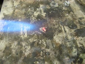
Heat treating the foot to soften it and remove any stress in the material. This also helps with the application of light bronzing to give the foot an aged look.
Stage 53
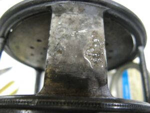
A nice effect after heat treatment.
This reel was a labour of love and I challenged myself to see if I could rebuild it and to make it work as well as possible. I also wanted it to look good and I think I have managed to do all of that. I have consent from the new owner to put this up on my web page. Before I sold the reel all of these photos were sent to the owner and I was more than happy to sell it a greatly reduced price. The reel is in his possession now and he is very happy with it